Was curious what's in the shielded box.
Couldn't find any service data or schematics. But this doesn't look all that complicated at first glance.
Couldn't find any service data or schematics. But this doesn't look all that complicated at first glance.
The other module is much simpler. No decoding logic needed there. Just fixed frequencies for markers
Flip side of the chassis. Besides regulated +-15V rails there's also some electronics that's connected to the external control connection
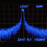
Plugged it in, line filter didn't blow up. Filter caps are fine, <25mV RMS ripple on -15V, <5mV RMS on +15V. There is no RF output from the upper unit, and only a CW at around 11 Mhz from the lower. No sweep. Adjusting the sweep width adjusts the frequency a bit. Time to trouble shoot with no schematics
🙏2
I've been procrastinating on posting what I've been up to. Let me try to recall where I was at with this repair
I reverse engineered the sweep generation circuit.
It gets its clock from the line voltage. There is a tap on the transformer for that. Starting in the upper left corner. The signal gets limited with a diode, then squared off with those two transistors. A 14538 dual mono stable vibrator is used to set the duty cycles.
One of those two signals then gets buffered, fed into an integrating capacitor, into a Schmitt trigger and eventually into an integrator to produce the ramp voltage needed for the sweep.