Second one has been worked on within this century! Interesting, so why is the case so dirty then and what's with the bomb?
The dial indicator is stuck on one of them because the bulb melted the plastics.... fun
I decided to work a bit on the RA-25U. The small one that's been worked on before. All iffy capacitors had been replaced, except one was missing completely and, well, the filter caps.. the schematic calls for two 50μF caps, which are the two sections of the electrolytic can. Since that is bad, they were replaced.. One with this 22μF, the other with this red paper bomb. Why?? Very much looks like a replacement done in the 60s or so. Why leave this in? I don't get it. Of course it was humming.
Bun's Lab
Photo
The RF section of the tuning capacitor was shorted. I pulled it, gave it a good clean. That fixed that issue.
The next problem is alignment. The local oscillator was out of whack on all three bands. I still haven't gotten the long wave band right. But before I go back and do it properly I figured I'll look at the IF sections first
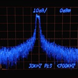
While I do have two wobbulators meant for this job, both are tube based and need work. So I went with a rather janky approach of using one function generator to generate a symmetrical ramp voltage, which I feed into both the x channel of a scope as well the VCF (voltage controlled frequency) input of another function generator, that is set to the 455 kHz IF frequency, causing it to sweep a symmetrical frequency range around the IF.
And while this method is great for seeing the shape of the filter response, it tells you nothing about the actual frequencies. You have no markers, unlike with a purpose build sweep generator like the Wavetek I showed before. Unfortunately, that one is of no use for AM radios, since it covers a frequency range of around 5 Mhz to 500 MHz.
Using a rather slow sweep frequency just as an example
This media is not supported in your browser
VIEW IN TELEGRAM
And increasing the sweep frequency